 Forme
Forme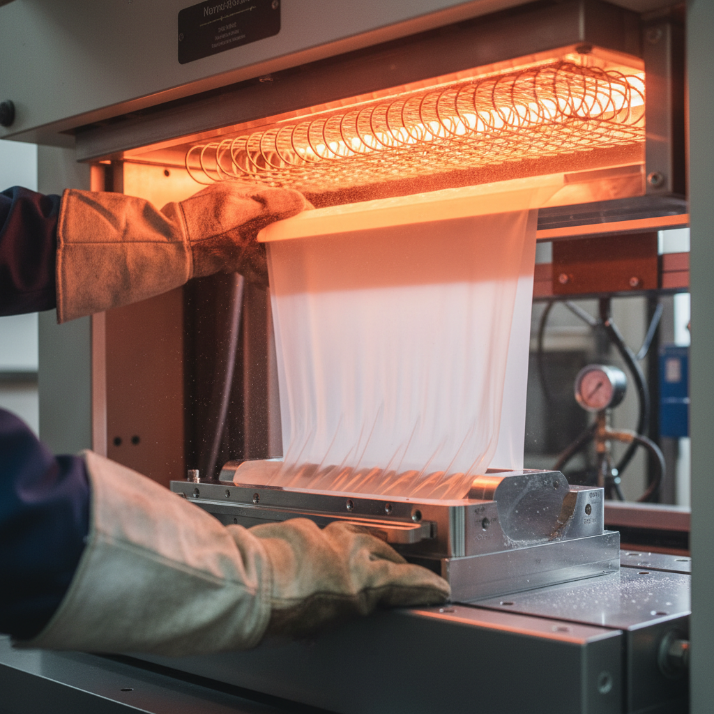
From sheet stock to finished part. Every step visible.
Vacuum
Forming
Machines.
Six stages.
One continuous
cycle.
Every Forme FP-series machine is engineered around the same six-stage cycle. Understanding each stage is how you spec the right machine — and how you run it at tolerance on day one. Scroll each section to see the engineering behind it.
Full forming cycle, nothing hidden
Heater zone temperature tolerance
Vacuum level across all models
Recipe storage, FP-2448 and up
Heating
Radiant energy, precisely delivered.
Stage Overview
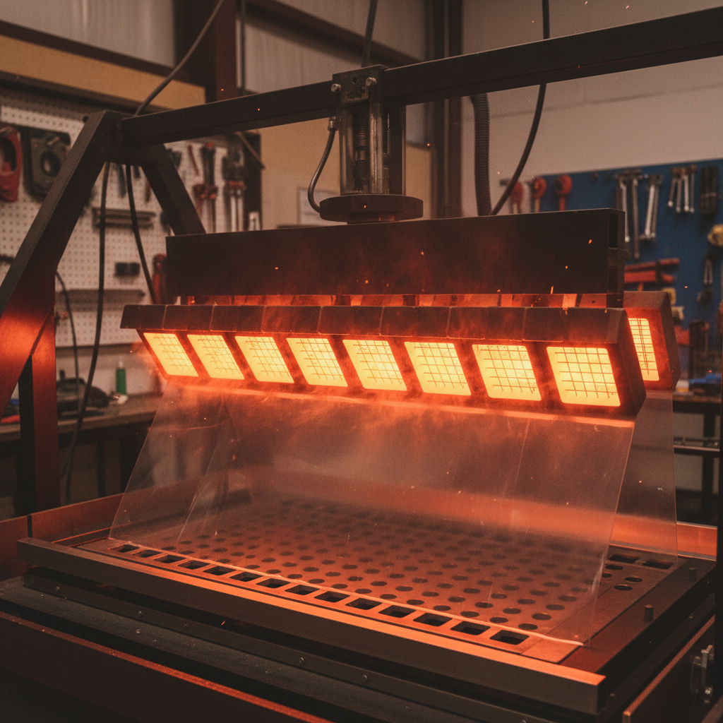
Ceramic infrared heaters in a zoned array bring the sheet to forming temperature uniformly across its full width. Each zone is independently PID-controlled to ±2 °C, compensating for material thickness variation and ambient temperature swings. The heater carriage travels on precision linear rails, maintaining a consistent 75 mm standoff regardless of sheet thickness.
Cross-section: Heater bank & sheet sag
Engineering Specifications — Heating Stage
| Parameter | Value | Notes |
|---|---|---|
| Heater Type | Ceramic Infrared (CIR) | Zoned array |
| Total Installed Wattage | 24 kW (FP-2448) | Up to 48 kW on FP-4896 |
| Temperature Control | ±2 °C per zone | PID closed-loop |
| Heater Zones | 6 independent zones | FP-2448 standard |
| Standoff Distance | 75 mm nominal | Fixed carriage rail |
| Heat-Up Time (cold) | < 4 minutes to 180 °C | Ceramic element |
| Pyrometer | Integrated IR sensor | Sheet surface reading |
Forming
Atmospheric pressure does the work.
Stage Overview
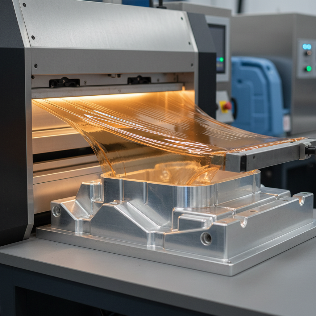
Once the sheet reaches forming temperature, the platen rises to engage the mold as the vacuum valve opens. Differential pressure between atmosphere (14.7 psi) and the evacuated cavity pulls the softened sheet into every corner of the tool. Plug-assist pre-stretching is available on all models, reducing wall-thickness variation on deep-draw parts from ±18% to ±6%.
Cross-section: Vacuum draw over mold
Engineering Specifications — Forming Stage
| Parameter | Value | Notes |
|---|---|---|
| Vacuum Source | Rotary vane pump | Oil-sealed |
| Vacuum Level | -28 inHg (94.8 kPa) | At platen surface |
| Pump Capacity | 15 CFM (FP-2448) | Up to 40 CFM on FP-4896 |
| Vacuum Tank | 60 L integral reservoir | Rapid draw-down |
| Platen Travel Speed | 0–120 mm/s | Servo-controlled |
| Plug Assist | Optional (all models) | Servo-driven Z-axis |
| Max Draw Depth | 300 mm (FP-2448) | 450 mm on FP-4896 |
Cooling
Locked in — before the part moves.
Stage Overview
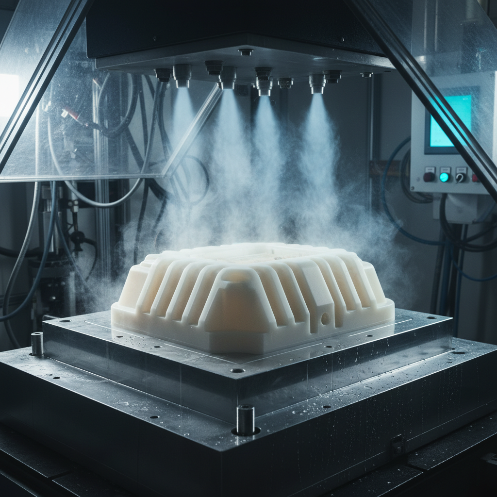
The formed part must cool below its heat-deflection temperature before ejection to hold dimensional accuracy. Forced-air manifolds flood both the exposed surface and, on molds with internal channels, the tool face simultaneously. Cycle time is directly tied to cooling efficiency; our dual-sided air blast reduces average cooling dwell by 35% compared to ambient-only methods.
Cross-section: Dual-sided cooling airflow
Engineering Specifications — Cooling Stage
| Parameter | Value | Notes |
|---|---|---|
| Cooling Method | Forced-air bilateral | Top + bottom manifold |
| Air Blast CFM | 120 CFM combined | Variable speed blowers |
| Mold Cooling Channels | Optional (tooling) | Water-cooled inserts |
| Typical Cooling Dwell | 8–22 seconds | Material & gauge dependent |
| HDT Monitoring | Mold thermocouple | Interlock to eject signal |
| Cycle Time Reduction | -35% vs ambient | Dual-sided blast |
Trimming
Clean edges, repeatable geometry.
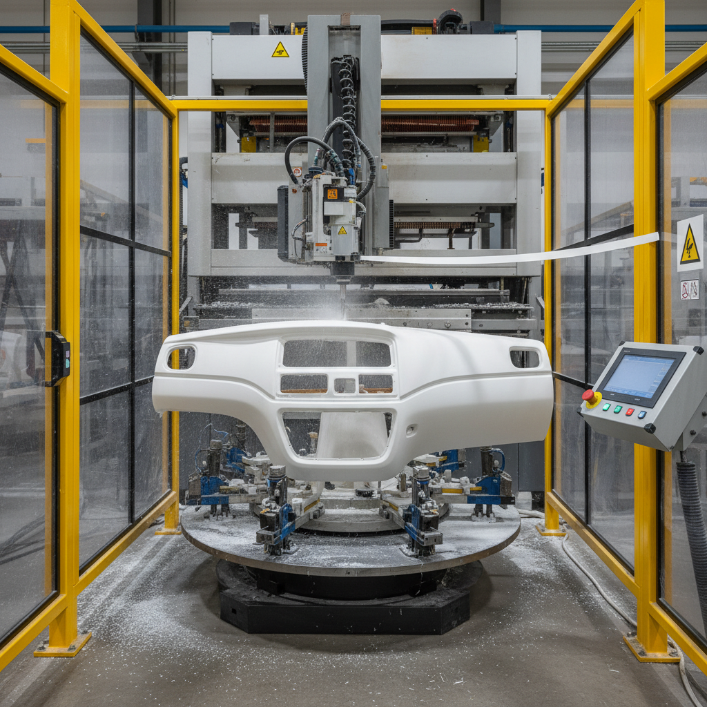
Stage Overview
Inline trimming stations remove the flange and skeleton web without secondary handling. CNC router trimming holds ±0.4 mm positional tolerance on contoured edges; steel-rule die punching suits high-volume flat-flange parts at cycle rates up to 600 parts per hour. Both methods are available as factory-installed options on the FP-series platen.
Cross-section: Router & die trim methods
Engineering Specifications — Trimming Stage
| Parameter | Value | Notes |
|---|---|---|
| Trim Method A | CNC 3-axis router | Contoured edges |
| Trim Method B | Steel-rule punch die | High-volume flat flange |
| Positional Tolerance | ±0.4 mm (router) | ±0.2 mm (die) |
| Max Trim Rate | 600 parts/hr (die) | Gauge dependent |
| Skeleton Winding | Optional web winder | Continuous roll feed |
| Dust Extraction | Integrated 3" port | Shop vac compatible |
Controls
Every variable logged. Nothing assumed.
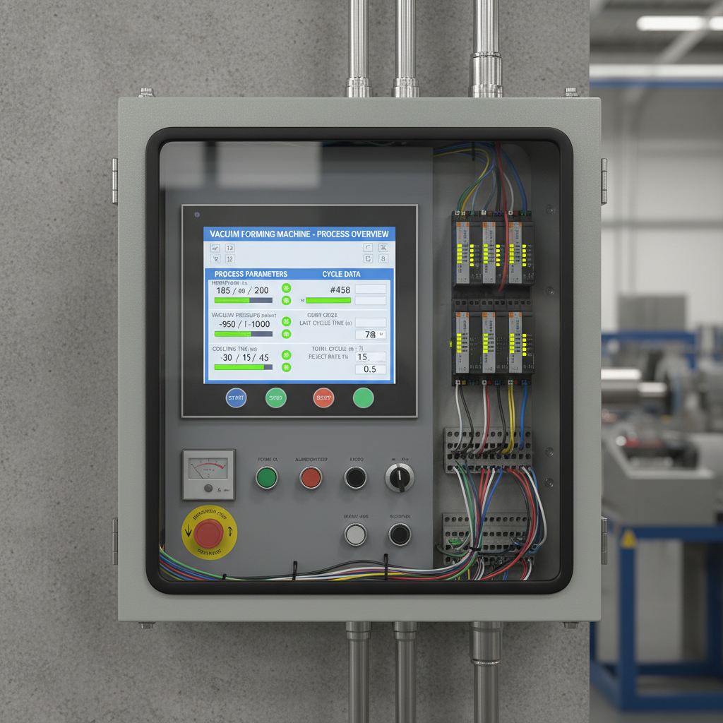
Stage Overview
The Forme FP-series control architecture is built on a Siemens S7-1200 PLC with a 12-inch touchscreen HMI running our FORMEware 3.2 interface. All process parameters — heater zone temperatures, vacuum level, platen position, cycle time — are logged at 100 ms resolution and exportable to CSV for SPC integration. Recipe storage holds 512 named jobs.
Controls architecture: HMI → PLC → Sensors
Engineering Specifications — Controls Stage
| Parameter | Value | Notes |
|---|---|---|
| PLC | Siemens S7-1200 | Safety-rated |
| HMI | 12″ capacitive touchscreen | IP65 rated |
| Software | FORMEware v3.2 | Recipe + data logging |
| Data Logging | 100 ms resolution | CSV export, 90-day onboard |
| Recipe Storage | 512 named jobs | USB backup/restore |
| Remote Access | VPN-ready Ethernet | Diagnostic port standard |
| Safety | Category 3 / PLd | E-stop, light curtain ready |
Tooling
The mold is where tolerance lives.
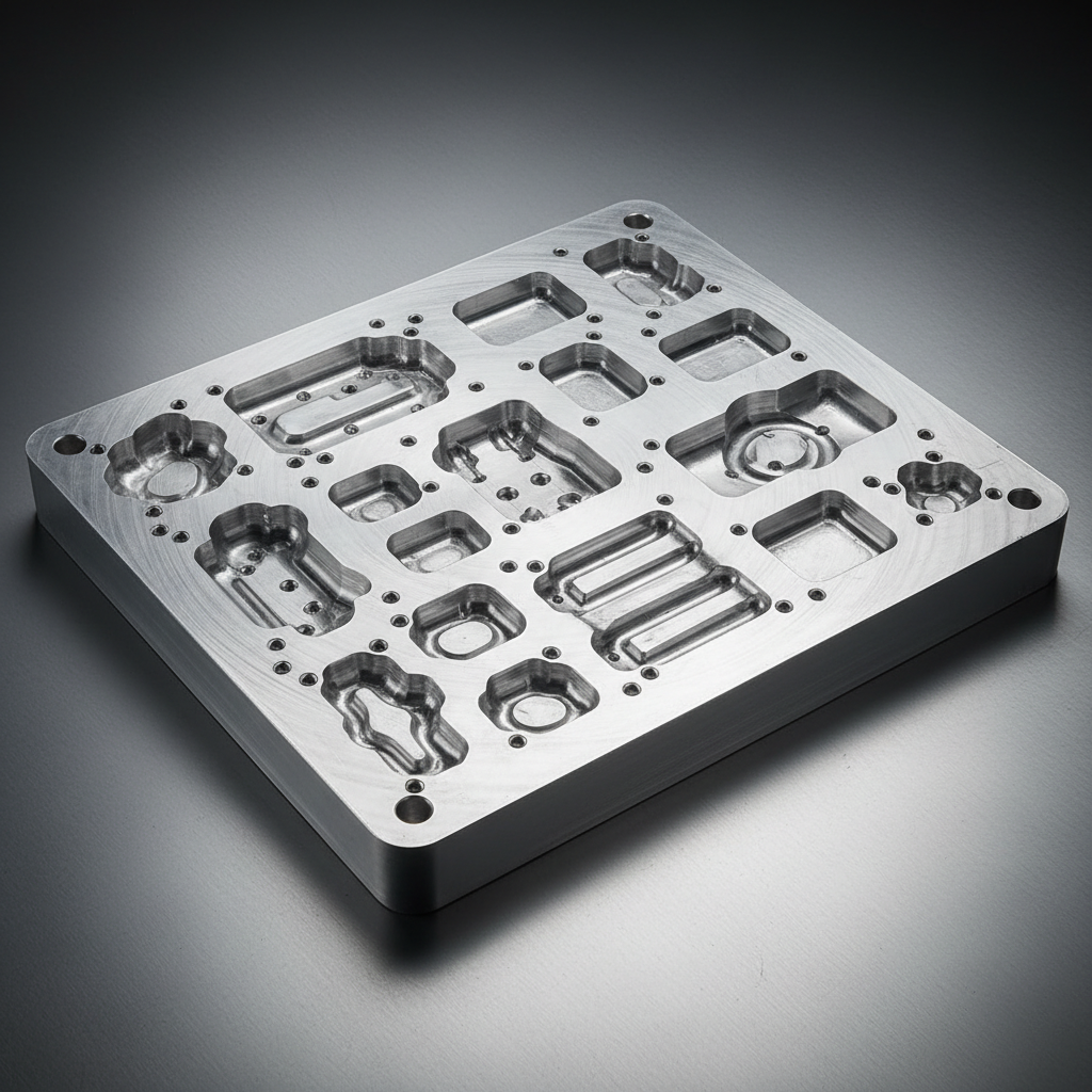
Stage Overview
All Forme molds are machined from 6061-T6 aluminum billet on 3-axis CNC mills to a Ra 1.6 µm surface finish. Vacuum ports are placed at the geometry's deepest draw points using our proprietary port-placement algorithm. Draft angles of 3° minimum are standard; tighter draws for medical and aerospace parts can be specified with electroformed nickel inserts at Ra 0.4 µm.
Cross-section: Mold geometry, ports, draft angles
Engineering Specifications — Tooling Stage
| Parameter | Value | Notes |
|---|---|---|
| Mold Material | 6061-T6 Aluminum | Billet CNC machined |
| Surface Finish | Ra 1.6 µm standard | Ra 0.4 µm (medical/aero) |
| Draft Angle | 3° minimum | Tighter on request |
| Vacuum Port Size | 0.8 mm diameter | Below material gauge |
| Port Placement | Algorithmic (deepest draw) | Proprietary method |
| Quick-Change | T-slot mounting plate | Sub-5-minute changeover |
| Nickel Insert Option | Electroformed, Ra 0.4 µm | Medical / aerospace |
Download the
Sizing Guide.
Match your sheet size, draw depth, and material type to the correct Forme FP-series model. Covers HIPS, ABS, PETG, PP, PC, and UHMWPE from 0.5 mm to 12 mm gauge. 36 pages. No fluff.
Three fields. No phone number. No pressure.
Models
Side-by-Side.
No account required. All specs are real production values, not marketing targets.
| Parameter | FP-1224 | FP-2448Selected | FP-3672 | FP-4896 |
|---|---|---|---|---|
| Platen Size (mm) | 305 × 610 | 610 × 1220 | 915 × 1830 | 1220 × 2440 |
| Max Draw Depth (mm) | 150 | 300 | 380 | 450 |
| Heater Wattage (kW) | 8 | 24 | 36 | 48 |
| Heater Zones | 2 | 6 | 9 | 12 |
| Vacuum Pump (CFM) | 6 | 15 | 26 | 40 |
| Vacuum Level (inHg) | -28 | -28 | -28 | -28 |
| Platen Travel Speed | 0–80 mm/s | 0–120 mm/s | 0–120 mm/s | 0–100 mm/s |
| Sheet Gauge Range (mm) | 0.5–6 | 0.5–10 | 1–12 | 1–12 |
| Plug Assist | Optional | Optional | Standard | Standard |
| Inline Trimming | — | Optional | Optional | Standard |
| Recipe Storage | 128 jobs | 512 jobs | 512 jobs | 512 jobs |
| Data Logging | Optional | Standard | Standard | Standard |
| Machine Footprint (mm) | 900 × 1400 | 1400 × 2200 | 1900 × 3100 | 2400 × 4200 |
| Power Supply | 240V / 1Ø | 480V / 3Ø | 480V / 3Ø | 480V / 3Ø |
| Target Application | R&D / Short run | Production / Mid-vol | High-volume | Large-format |